Adding USB-C to my HP Prime graphing calculator
Update 1/7/2026: This article has been featured on Hackaday.com!
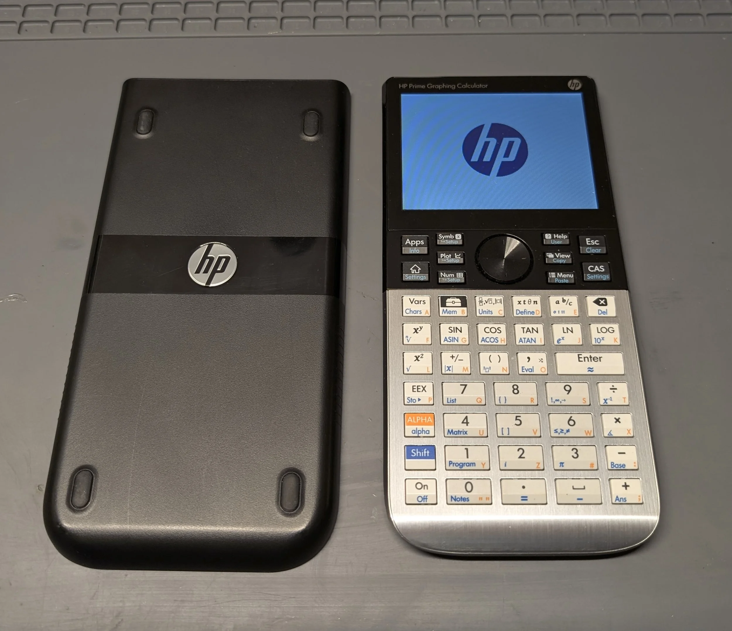
About a year ago, I switched graphing calculators from my trusty TI-84+ to a shiny new HP Prime G2. After an initial learning curve, (the TI-84’s button layout was deeply ingrained in my muscle memory) I quickly grew to appreciate the HP’s far superior capabilities. The high-resolution color LCD screen fits more equations with better formatting than the TI-84 could ever dream of. I appreciate having a CAS (computer algebra system,) and I find this calculator’s interface far more convenient than my computer keyboard’s for entering complex mathematical expressions. For my electrical engineering coursework, I added a custom macro to find parallel resistor values. This feature has been an enormous time-saver, and I use it constantly.
I do have a few gripes with this calculator however:
1) Unlike my TI-84+, which had battery life measured in months, I must recharge my HP Prime on a weekly basis. Additionally, despite being sold in 2025, HP Primes still have Micro-USB ports! This meant that I needed to carry a dongle everywhere I go, lest I run out of battery life while taking an exam or completing an important homework assignment. Eventually, I had enough of this anachronism and decided to modify the calculator so that it has a USB-C port of its own.
Note: The HP Prime uses a battery that is compatible with the Samsung Galaxy S3. As an experiment, I’d like to try swapping a higher capacity 3000mAh battery into the calculator in the future as a way to further extend the battery life.
2) The LCD in the calculator is a far cry from a fancy IPS or OLED panel. The backlit picture is washed-out and grainy, with exceptionally poor viewing angles for a pricey modern device. Apparently, according to a forum post made by members of the calculator’s design team, the LCD panel was installed upside down inside each device, against their wishes. This design compromise allegedly allows for easier internal cable routing. Unfortunately, such a compromise ruins the viewing angles of an already poor quality LCD. I hope to someday replace my calculator’s LCD panel with an IPS alternative, but doing so will require a custom interposer board and FPGA to adapt the digital video signals. This task is made even more complex by the need to contend with a separate capacitive touchscreen digitizer as well. Additionally, the original display seems to be affected by RF interference and often afflicted by jitters. A future modification will likely need to tolerate noisy input signals.
3) The calculator is usually stable, but does crash often enough I feel the need to make note of it here. A quick reboot resolves these issues, but it is unfortunate that crashes happen at all. On the bright side, the software for the HP Prime is still in active development.
Moving on to my USB-C mod!
The USB-C adapter board I purchased (photo credit to amazon seller)
I found some inexpensive adapter boards on Amazon that promise to adapt micro-USB sockets into USB-C ports. The premise is that the original port can be be desoldered, and a new USB-C port can be soldered in its place. This sounds easy in theory, but in reality, things are always a little trickier.
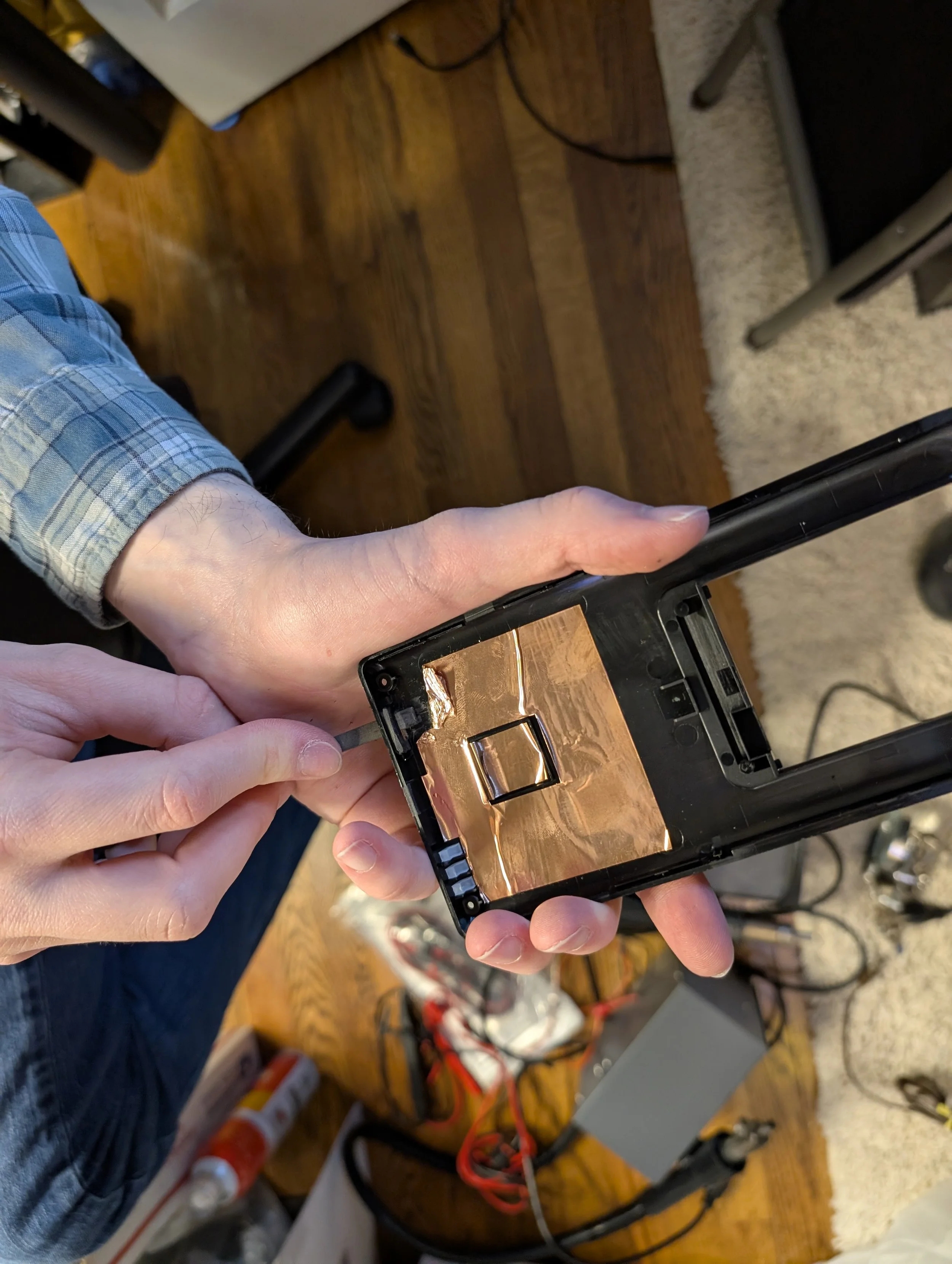
I began by disassembling the calculator. It is held together with a handful of phillips head screws, as well as a series of plastic clips around the perimeter of the housing. I used a spudger to pry the housing open. There are two PCBs within the calculator, one for the keypad, and another for the bulk of the circuitry. Unfortunately, the micro-USB socket’s PCB is glued to the LCD panel. I was unable to separate the two without risking damage to the LCD, so I decided to work with the PCB still attached. The entire PCB was covered in a layer of yellow kapton tape, which I made sure to replace after completing the mod. Additionally, there was a layer of copper tape adhered to the plastic housing opposite the main PCB (presumably for EMI shielding purposes). I believe the kapton tape ensures the PCB doesn’t short out against the copper shielding.
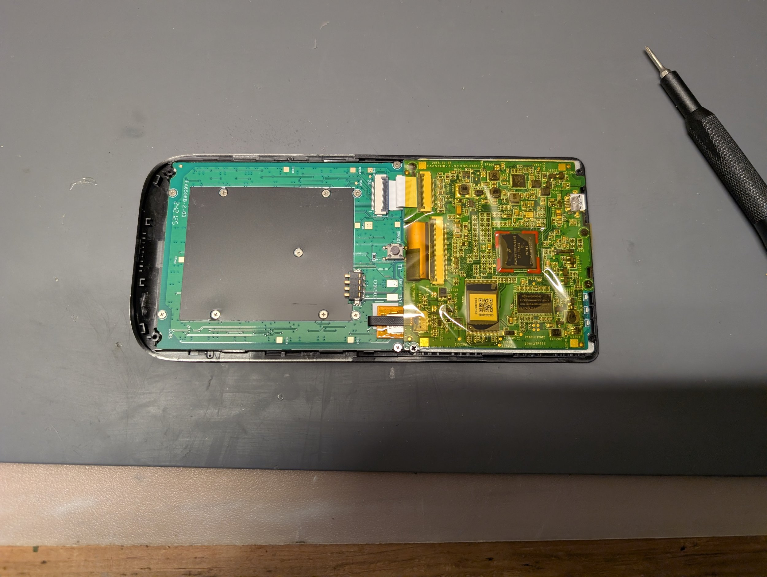
Peeking inside the HP Prime
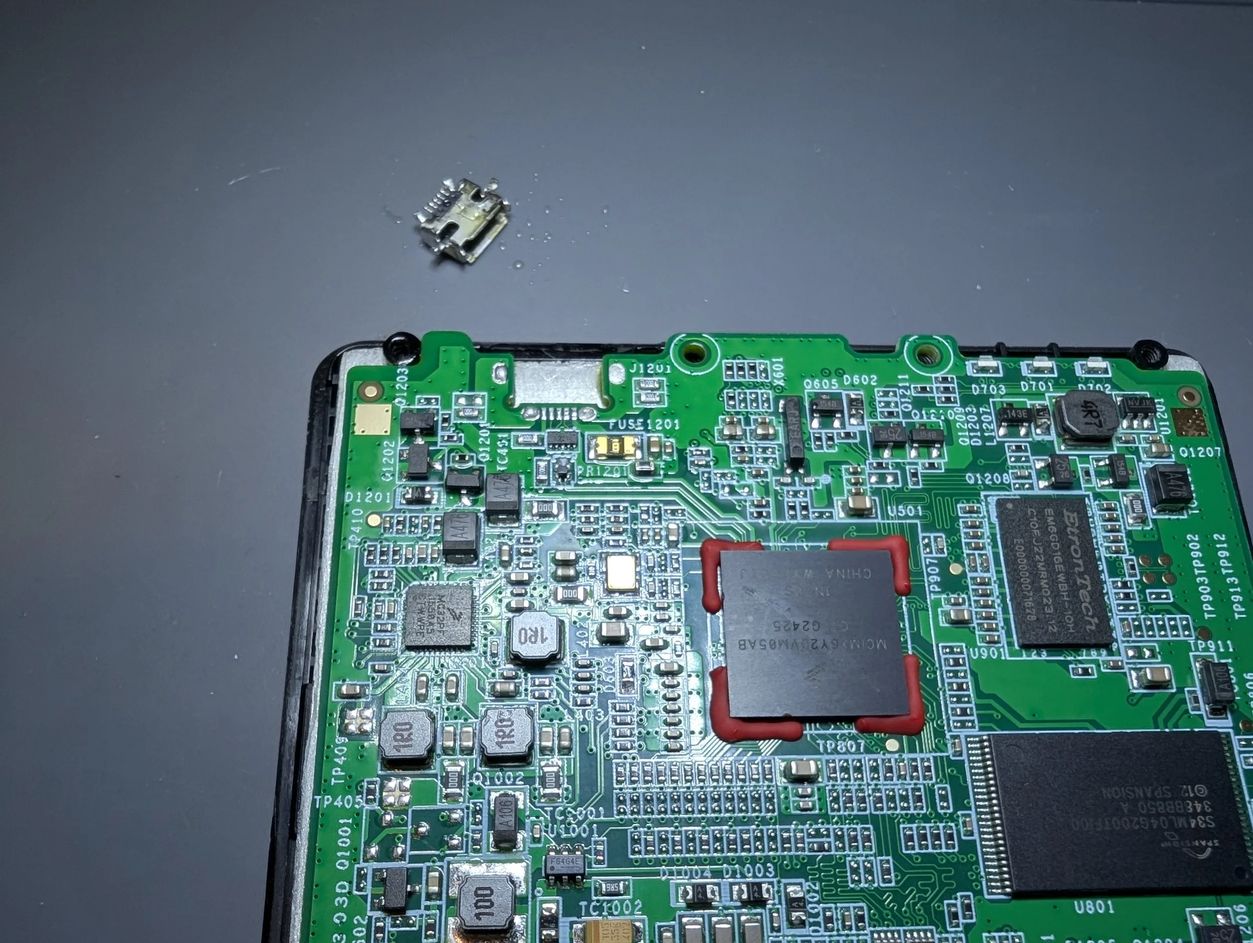
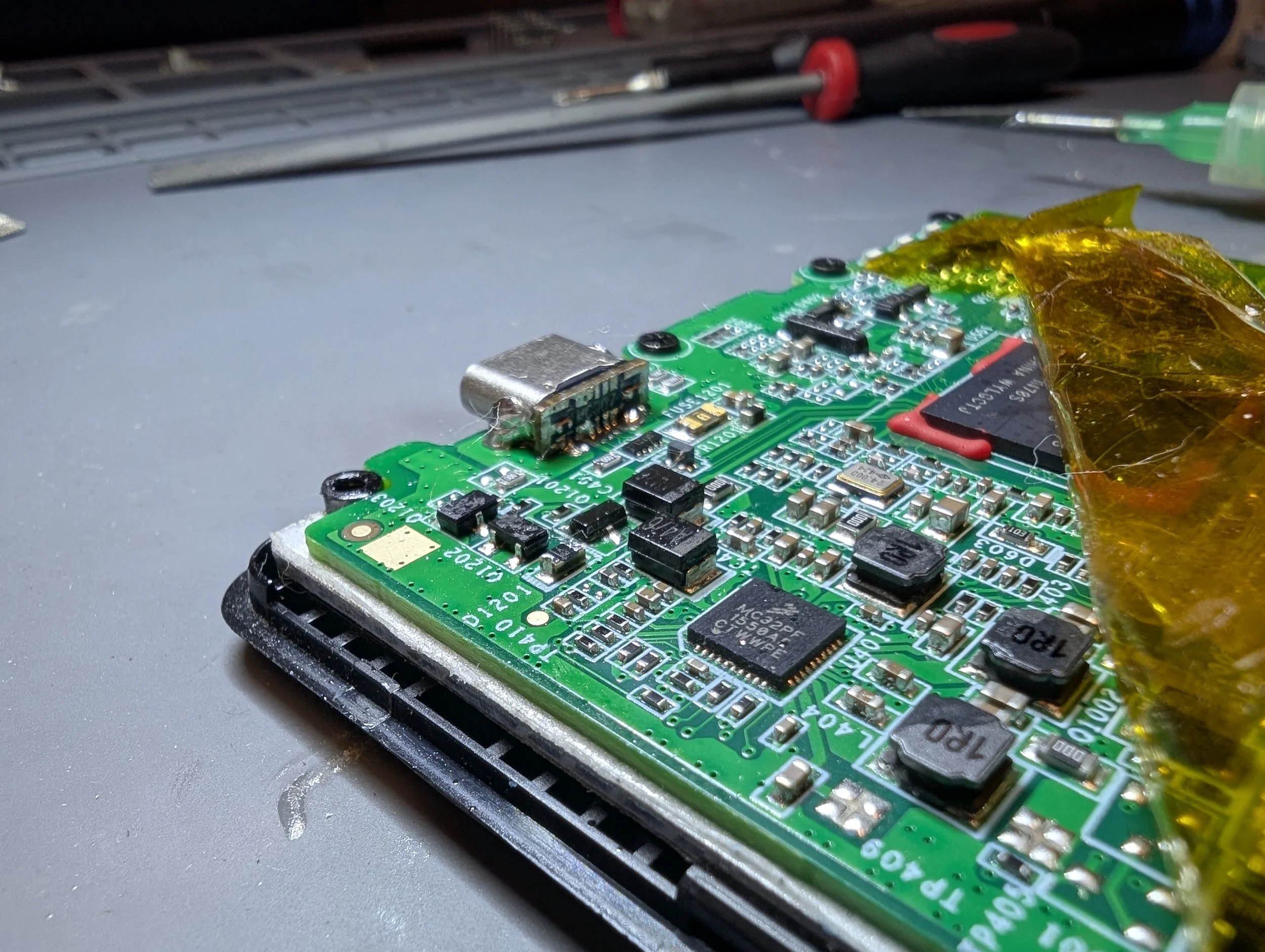
Desoldered micro USB port
Working under a microscope with the aid of a hot air rework station, I was able to carefully desolder the original micro-USB socket. Because there are several nearby ground planes in the PCB, this took a fair amount of time and heat. I was careful to avoid overheating the calculator’s plastic housing or allowing liquid/flux to enter the nearby LCD panel.
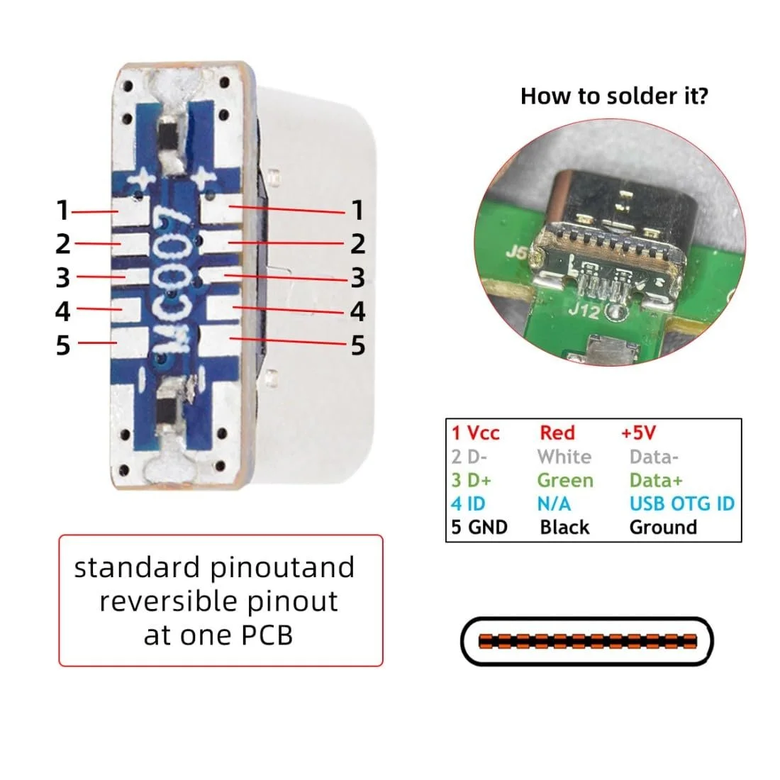
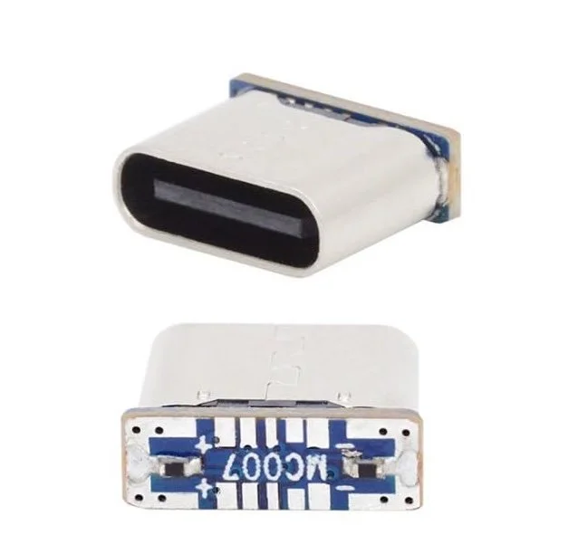
Adapter Pinout from Amazon seller
Once I had removed the micro-USB connector, I did some probing with a multimeter to determine the wiring of the PCB traces. I found that the leftmost pad was tied to ground, and the rightmost pad was tied to +5V. Examining the PCB attached to the USB-C adapter, I oriented “plus” and “minus” silkscreen markings to match the pad layout on the HP Prime PCB.
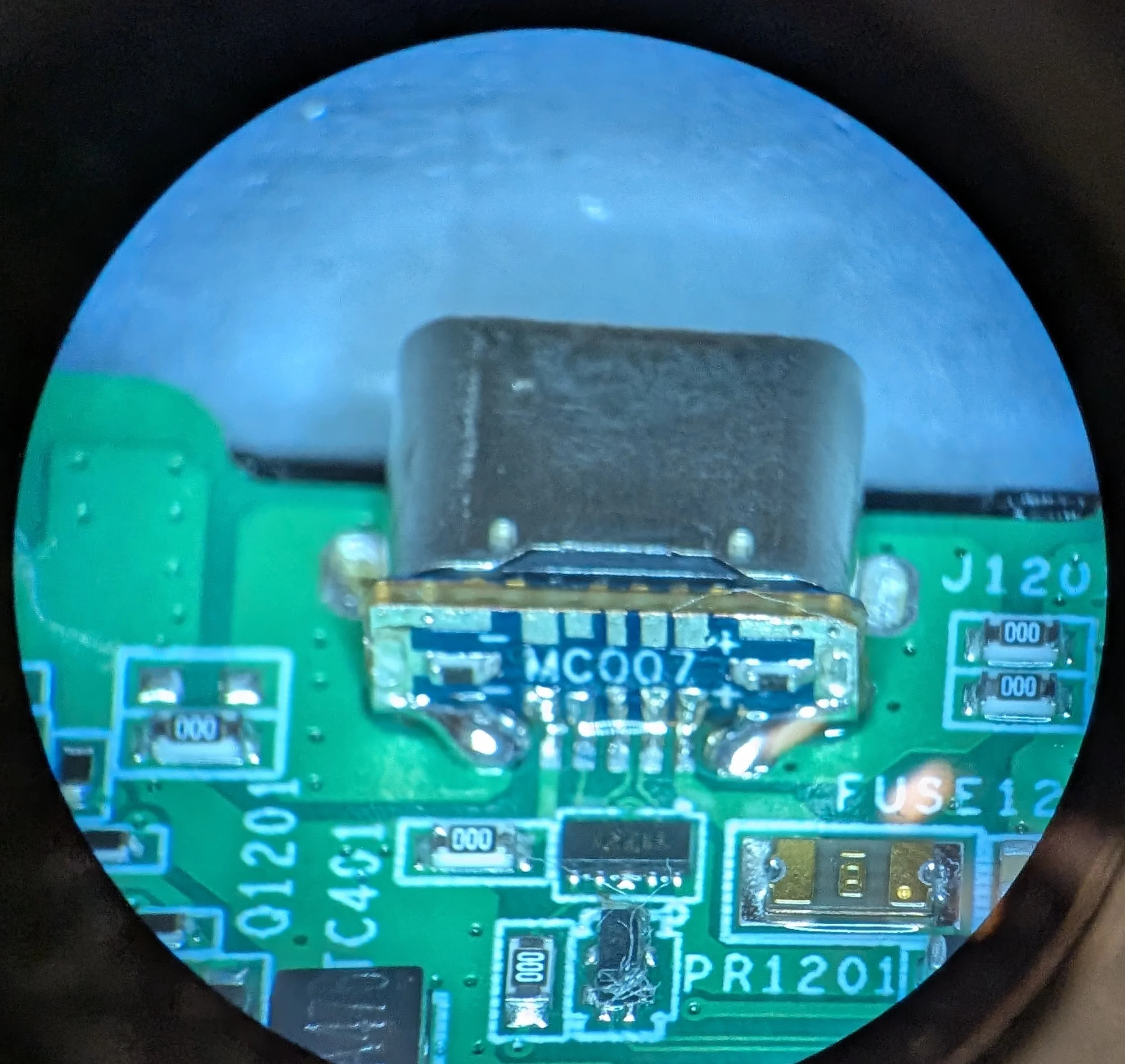
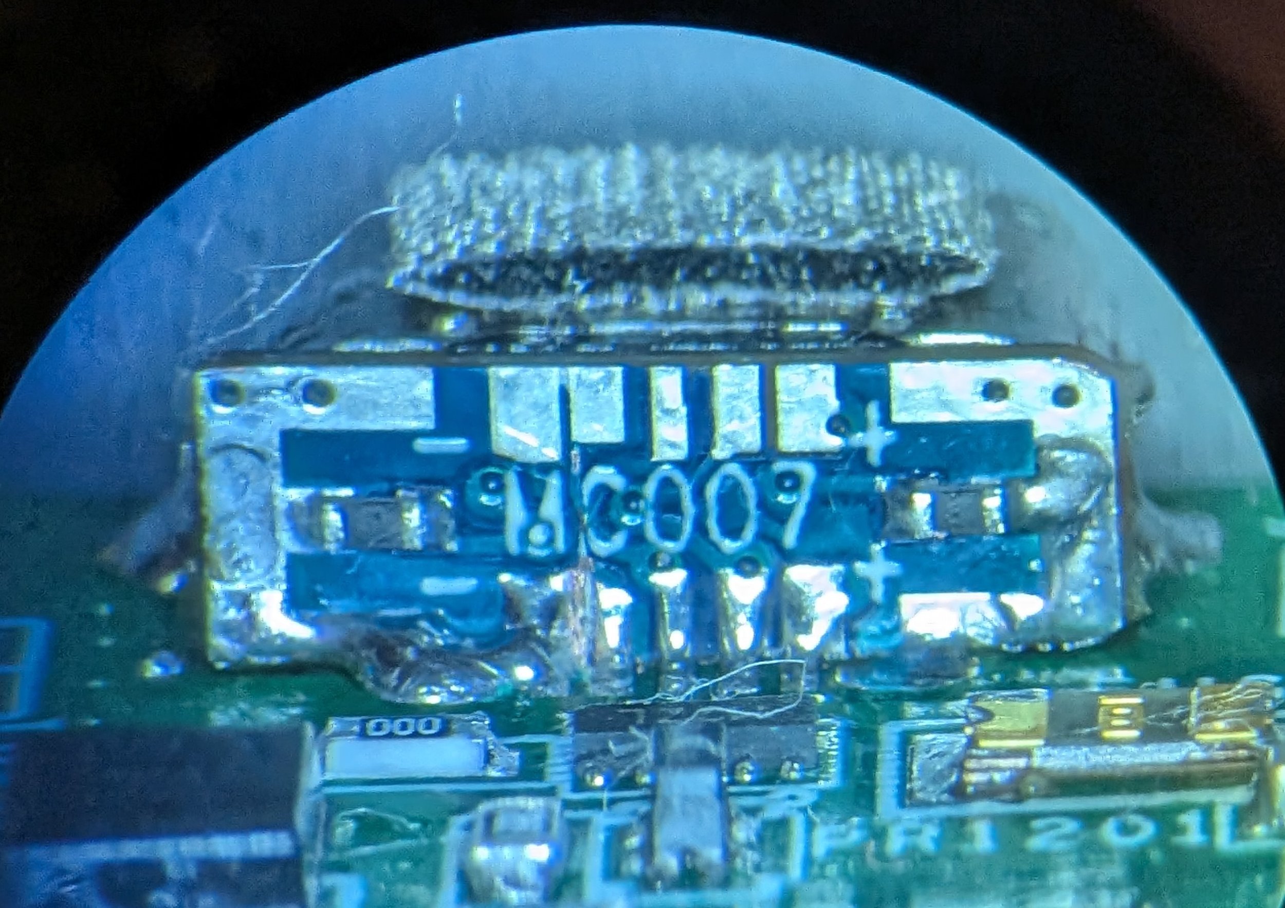
The surface mount pads were absolutely tiny! I’m glad to have a microscope at my disposal, as this project would be far trickier without one. It took a surprisingly large amount of heat to bond the ground plane pads with the USB-C connector. My smallest SMD soldering iron tips couldn’t keep up, so after connecting the data pads, I resorted to a large knife-style soldering iron tip to mount the USB-C port securely in place. After I carefully soldered each of the pads from the USB-C adapter to the HP Prime PCB, I gave the modification a test. Aaaaaaaaaannd… it didn’t work!!!
Although USB-C power would boot the calculator, and the USB-C 5.1k CC1 and CC2 resistors functioned, the HP Prime’s battery would not charge, and USB data transfer was broken. Breaking out my USB multimeter, I found that while the calculator was being supplied with 5V of power, the D+ and D- data lines were at the wrong levels (about 0.5V instead of 3.3V). The calculator frequently crashed, displaying a spinning hourglass icon in the upper-right hand corner of the LCD. Connecting the HP Prime to my computer, I was unable to detect the USB device in the System Information app.
After extensive troubleshooting, I discovered an issue with the USB-C adapter board design. One key difference between the Micro-USB and USB-C pinouts is that many Micro-USB devices implement a feature called USB OTG (on-the-go). Depending on the signal sent to to the USB OTG ID pin, the calculator would function either as a USB host or as a USB peripheral.
For my use case, the HP Prime only ever needs to function as a peripheral. Unfortunately, it seemed to be stuck in host mode! The adapter PCB’s original design tied the USB OTG ID pin to ground. This was why it was not able to mount on a computer, and rather than accept power from chargers, the calculator was trying to provide it to them. After cutting this offending trace under a microscope, the HP Prime USB-C port was fixed. Compared to the size of the USB OTG ID trace, my finest scalpel blades seemed enormous. Thankfully, I managed to sever the connection without causing any accidental damage (I had to zoom my microscope all the way in).
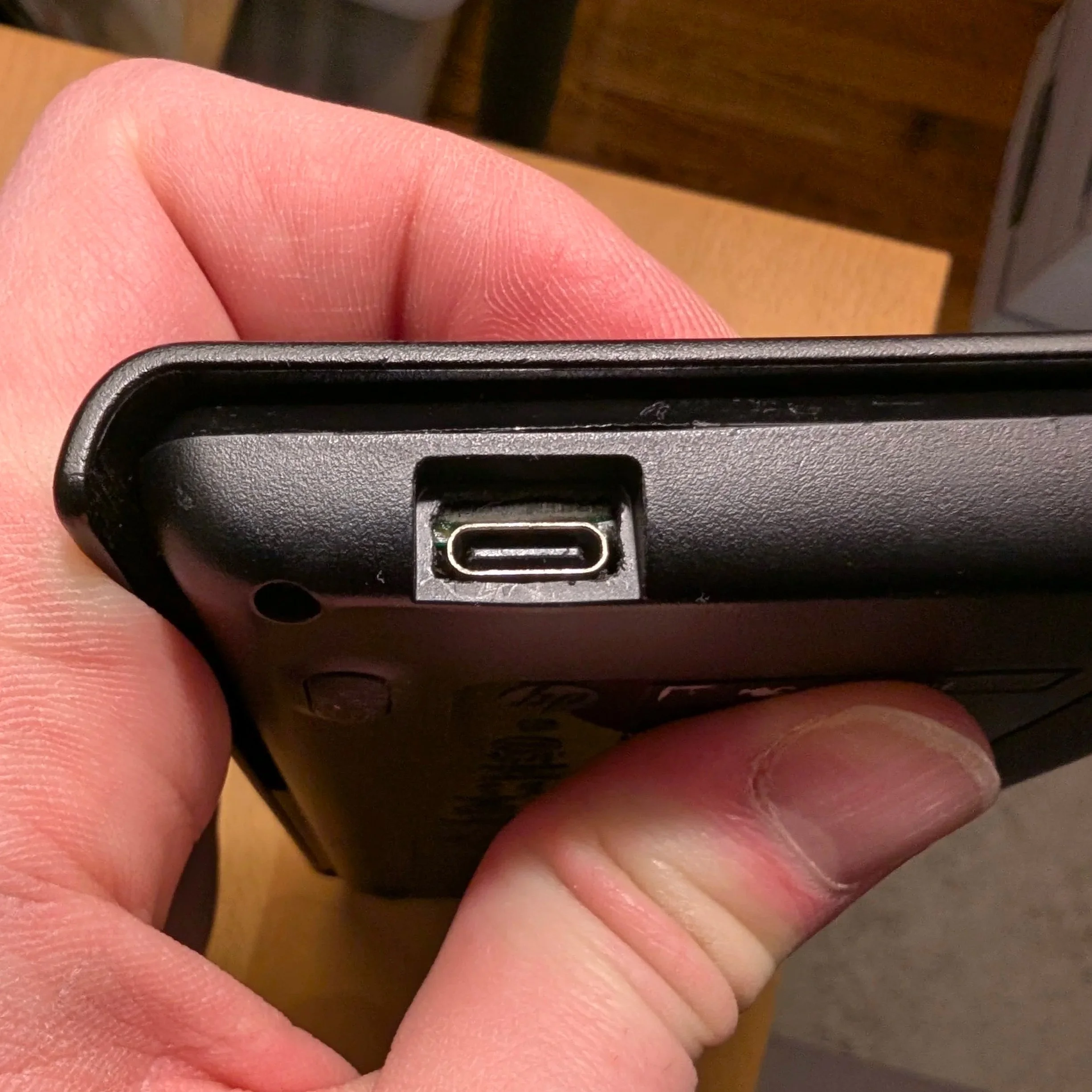
Afterwards, I used a needle file set to enlarge the plastic housing of the HP Prime. While the USB-C port appeared to fit without any modification to the case, the spacing was much too tight, and the housing refused to clip closed. Also, a lot of pressure was being placed on the USB-C connector, which was not good for long-term durability. As a finishing touch, I transplanted the original EMI shielding from the micro-USB connector onto the USB-C connector.
After all that tinkering, it finally works! Was this mod worth it? Probably not. But now I have a custom USB-C calculator, and it makes me happy, so that’s what counts.